10+ fft block diagram
Cyclone 10 GX FFT to iFFT with Natural Input and Output Orders Using Cosine Data Example Design. This operation is useful in many fields but computing it directly from the definition is often too slow t.

Tao Qin Microsoft Research
The Butterfly Diagram is the FFT algorithm represented as a diagram.

. FFT block diagram 2-point DFT 2-point DFT 2-point DFT 2-point DFT Merge two 2-point DFTs Merge two 2-point DFTs Merge two 4-point DFTs. FFT As a result we have seen that the breaking up a large DFT into two smaller DFTs will allow savings in computations. Fourier analysis converts a signal from its original domain often time or space to a representation in the frequency domain and vice versa.
We have structurally built the FFT block by. Aynchronous top level block diagram The top-level block diagram of the Asynchronous version of the FFT4 design is as given in above figure. If the signal level is too high then clipping and distortion.
The design mainly consists of. Here I have given very simple explanation of how the butterfly diagram for 2 p. This process is demonstrated by the block diagram below.
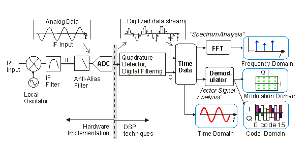
Block diagram of modules in the reference design Figure 2 shows the high-level. The FFT analyzer requires attenuators of gain stages to ensure that the signal is at the right level for the analogue to digital conversion. FFT analysis is one of the most used techniques when performing signal analysis across several application domains.
Decimation in Time is an FFT algorithm which is used to calculate DFT easily. The FFT block implements the signal flow diagram. Its the basic unit consisting of just two inputs and two outputs.
A fast Fourier transform FFT is an algorithm that computes the discrete Fourier transform DFT of a sequence or its inverse IDFT. The signal recovered after Fast Fourier transform is often called as periodogram. The DFT is obtained by decomposing a sequence of values into components of different frequencies.
FFT 7 8 is useful tool in digital signal analysis because it helps to reduce computational complexity. FFT transforms signals from the time domain to the frequency domain. FFT Block Control Class.
First here is the simplest butterfly. The FFT block is the main block which do the conversion of domain. The FFT allows signal gain adjustment in a fixed-point environment by using a block representation of input values of block size N to an N-point FFT.
This algorithm is applied. The FFT block is an RFNoC block that accepts signed complex 16-bit data at its input and computes the forward or reverse FFT of the input data outputting signed. 2277-9655 Mehrotra et al.

102 Questions With Answers In Fast Fourier Transform Science Topic

102 Questions With Answers In Fast Fourier Transform Science Topic
Vector Signal Analyzer Wikiwand

What Is A D Converter How To Wire It
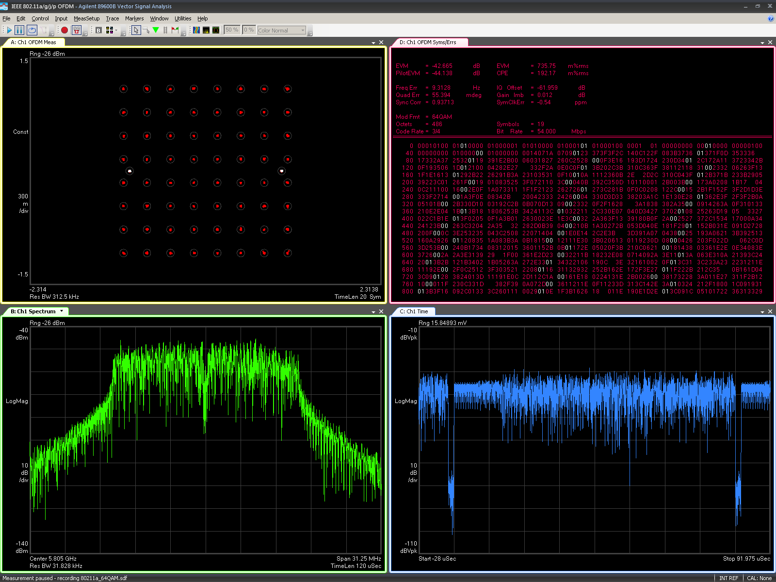
Vector Signal Analyzer Wikiwand

Telecommunications
![]()
Fourier Transform Infrared Spectroscopy Wikiwand
Vector Signal Analyzer Wikiwand

Fourier Transform Infrared Spectroscopy Wikiwand

Advanced Video Coding Wikiwand
2
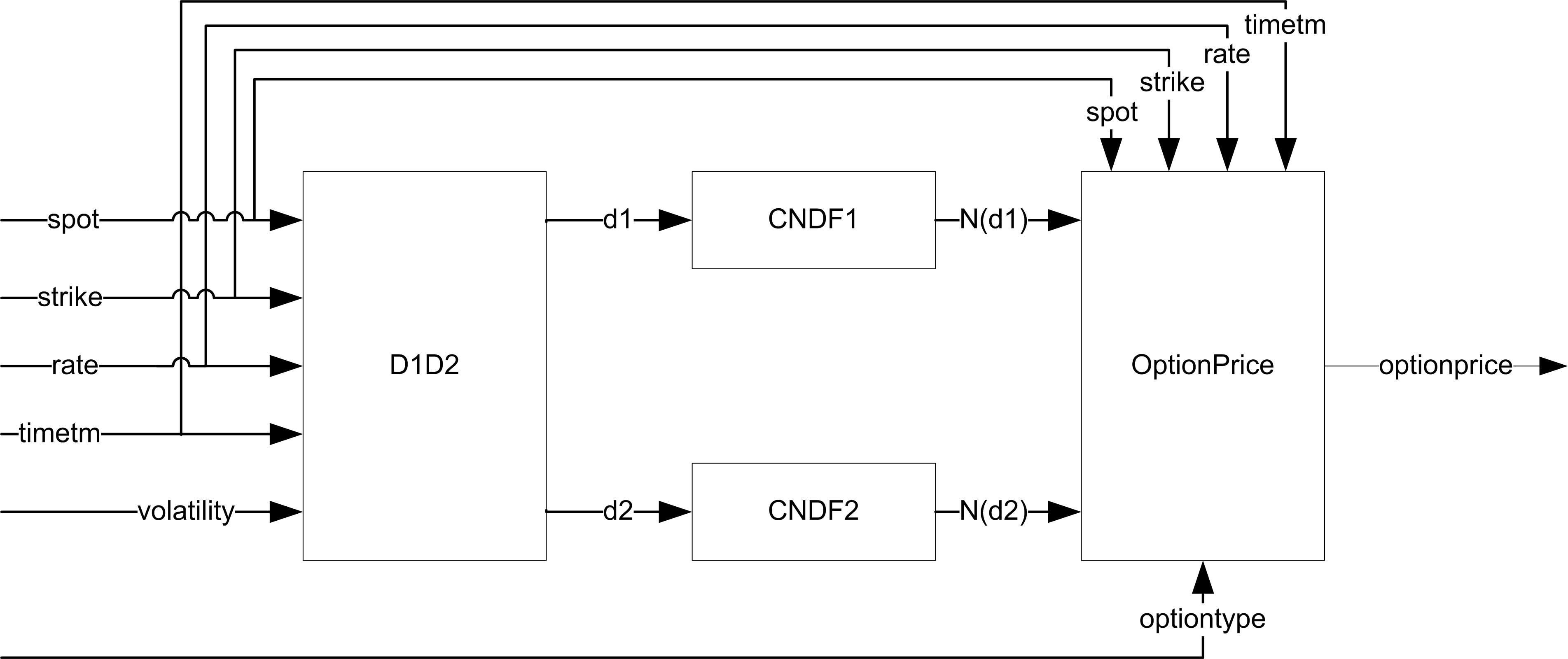
Black Scholes In Hardware
Proposed Transceiver Block Diagram With Shaded Area Showing The Scope Download Scientific Diagram
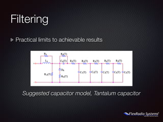
N5ac 2015 Huntsville Hamfest Flexradio Systems

102 Questions With Answers In Fast Fourier Transform Science Topic
Why Does A Sinusoidal Signal In The Time Domain Have Two Frequency Responses In The Frequency Domain Quora

Transform Time Domain Data Into Frequency Domain Matlab Simulink Data Frequencies Domain